This page describes the hardware architecture of the computer system on which
your operating system runs. You won't actually be running your OS code on
hardware, but will be adding it as part of some software that simulates the
hardware architecture. However, to understand how the simulator is structured
and how it behaves, you need to understand the hardware architecture being
simulated.
To avoid dealing with the mind-numbing array of brain-damaged gotchas real
computer architectures lay in the OS implementor's path, the hardware
architecture described here is a combination of generic computer-architecture
features; the whole is not representative of any real computer architecture.
However, some architectural features, particularly the idea of making
everything accessible by mapping into Primary Store, are based on Digital
Equipment Corp.'s Compaq's HP's PDP series of minicomputers.
The over-all structure of the architecture is given by the following diagram:
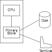
There are four hardware components
in the architecture: the CPU, the Primary Store, a disk, and a terminal. Of
these four components, the Primary Store can be thought of as being the main
component because all other components in the architecture are accessible
through Primary Store.
The
word is the fundamental unit of storage; the hardware cannot
directly deal with any quantity smaller than a word. A word consists of 32
bits, numbered 0 to 31 from right to left in the word; bit 0 is the rightmost
(least significant) bit, bit 31 is the leftmost (most significant) bit. A word
can also be thought of as consisting of 4 8-bit bytes, numbered 0 to 3 from
right to left in the word; byte 0 is the rightmost (least significant) byte,
byte 3 is the leftmost (most significant) byte. Within each byte, bits are
numbered from 0 to 7 in right to left order.
Primary Store is represented as an array of words. The index associated with
each word is also known as the word's
address. The arrays are indexed
as they are in C: starting from zero and increasing by 1 for each successive
array element.
Primary Store is partitioned into three contiguous subarrays known as the
the
System Space, the
User Space, and the
Device Space:
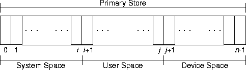
These three areas are called "spaces" to emphasize that they are part
of Primary Store.
Each space is defined by three constants: s_base,
s_base, and s_base, where s is one of
sys, usr, or dev. The constant values represent
- s
_base: The lowest accessible address in the associated space.
- s
_size: The number of words in the associated space.
- s
_top: One more than the highest accessible address in the
associated space; that is s_top = s_base + s_size.
sys_base is the lowest accessible address in Primary Store and
dev_top is one more than the highest accessible address in Primary Store.
Note also that sys_top == usr_base and usr_top == dev_base.
User Space is divided into 32 page frames, where each
page frame
consists of 32 consecutive words of user space. Page frames are numbered
from 0 to 31 with page frame 0 starting at Primary Store address 1024 and
page frame 31 ending just before address 2048.
The two components of interest in the CPU are the CPU register set and the
clock.
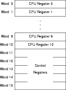
The CPU contains a set of sixteen
CPU registers (or just registers when
the context is clear). The CPU registers are mapped into the first sixteen
words of System Space and are accessed like any other word of Primary Store.
The hardware uses the contents of five of the CPU registers to control various
aspects of process execution; the hardware ignores the contents of the
remaining eleven registers. The arrangement of registers in Primary Store is
The five registers used by the hardware are (the constant name in parenthesis
is the address of the register)
-
Base Register (
base_register) - The hardware interprets the contents of
the Base Register as the lowest legal address accessible to the currently
running process.
-
Top Register (
top_register) - The hardware interprets the contents of the
Top Register as one more than the highest legal address accessible to the
currently running process.
-
Invalid-Address Register (
ia_register) - Whenever an address triggers an
invalid-address interrupt, the hardware stores the offending address in the
Invalid-Address Register
-
Program Counter Register (
pc_register) - The hardware interprets the
contents of the Program Counter Register as the address of the next instruction
to execute.
-
Program Status Register (
ps_register) - The hardware interprets the contents of the
Program Status Register as a representation of the currently running process's
current state.
The interpretation of the bits within the Program Status Register is
- bit 0
- Virtual memory indicator. If bit 0 is one, user processes
are run in virtual memory with paging enabled. If bit 0 is zero, user
process are run in User Space with paging disabled.
- bit 1
- If bit 1 is one, the most recent CMPR instruction found the
greater-than relation. If bit 1 is zero, the greater-than relation
didn't hold for the most recent CMPR instruction.
- bit 2
- If bit 2 is one, the most recent CMPR instruction found the
less-than relation. If bit 1 is zero, the less-than relation didn't
hold for the most recent CMPR instruction.
- bit 3
- If bit 3 is one, the most recent CMPR instruction found the
equality relation. If bit 1 is zero, the equality relation didn't hold
for the most recent CMPR instruction.
- bits 4 through 7
- Undefined and reserved for future use.
- bits 8 through 15
- (Byte 1) The id of the executing process.
- bits 16 through 31
- Undefined and reserved for future use.
Bits are numbered from right to left in a word; bit 0 is the rightmost bit in a
word.
The
CPU clock is an unsigned, 32-bit value that is increased by one
every time an instruction is executed. The unit of time for this clock is
called the
clock tick, or usually just "tick". When the
hardware is rebooted, the clock is set to zero.
The clock is controlled by a set of two clock registers mapped into a group of
two words in Device Space:
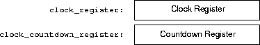
The constants clock_register and clock_countdown_register give the
Device-Space addresses of the associated clock registers.
The function of each clock register is
-
Clock Register
- The Clock Register contains the current time in ticks.
The Clock Register is a read-only register; writing a value to the Clock
Register has no effect; in particular, it doesn't change the time.
-
Countdown Register
- Writing a positive integer n to the Countdown
Register causes a clock interrupt n clock ticks from now. Writing a
positive integer n to the Countdown Register cancels a current countdown
if it exists and starts a new countdown.
Writing a non-positive integer to the Countdown Register cancels any countdown
currently in progress. If no countdown is in progress, writing a non-positive
integer to the Countdown Register has no effect.
The
Halt Register determines when system execution stops. The Halt
Register is mapped into a word in Device Space:
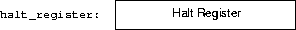
The constant halt_register gives the Device-Space addresses of the Halt
Register.
Writing a value, any value, into the Halt Register ends simulator execution.
The
Memory Management Unit (
MMU) contains an array called
the
page table. The page table contains pages_in_user_space
elements; each array element of the page table is a
page-table
entry. The i-th element in the page table corresponds to the
i-th page fame in user space. The fields in a page-table entry are
-
accessed_at
- An unsigned value containing the most recent time at
which the corresponding page was read or written.
-
modified_at
- An unsigned value containing the most recent time at
which the corresponding page was written.
-
page_number
- An unsigned value giving the page number of the
page resident in the page frame associated with this page-table entry.
-
valid
- A boolean value indicating whether or not the contents of
this page-table entry are valid.
-
process_id
- A byte value indicating to which process this page-table
entry applies.
All fields can be manipulated by the operating system. The hardware also
automatically sets accessed_at and modified_at on each reference
to valid page-table entries.
A
disk block is a non-empty array of words. A
disk is a
non-empty array of disk blocks. Disk-block and disk arrays are indexed as they
are for C: starting from zero and increasing by one for each successive
element. The size of the disk is fixed; that is, the number of disk blocks in
the disk does not change. The constant disk_size gives the number of
blocks in a disk. The size of each disk block is also fixed; all disk blocks
in a disk have the same size. The constant disk_block_size gives the
number of words in a disk block.
A disk is controlled through a set of four
disk registers mapped into a
group of four words in Device Space:
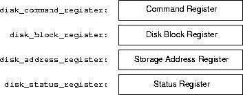
The constants disk_command_register, disk_block_register, disk_address_register, and disk_status_register give the
Device-Space addresses of the associated disk registers.
The function of each disk register is (the constant name in parenthesis is the
Device-Space address of register)
-
Disk command register (
disk_command_register) - Writing a value to the Disk Command
Register starts a disk operation.
Writing the value device::read to the Disk Command Register initiates
disk input: the disk block at the address contained in the Disk Block Register
is moved from the disk to Primary Store starting at the address contained in
the Disk Address Register.
Writing the value device::write to the Disk Command Register initiates
disk output: the data from the sequence of words starting at the address given
in the Disk Address Register and continuing through the size of a disk block is
copied from Primary Store and written to the disk block at the address
contained in the Disk Block Register.
Any value other than device::read or device::write written to the
Disk Command Register is interpreted as an illegal command code.
-
Disk Block Register (
disk_block_register) - The Disk Block Register contains the address
of a disk block. Whether the addressed disk block is read from or written to
the disk depends on the command written to the Disk Command Register.
-
Disk Address Register (
disk_address_register) - The Disk Address Register contains the
lowest address in a sequence of n Primary Store addresses, where n is
the size of a disk block in words. Whether the contents of the sequence is
written to disk or replaced by data read from the disk depends on the command
written to the Disk Command Register.
-
Disk Status Register (
disk_status_register) - The Disk Status Register contains the
status of the most recently issued disk i-o operation. The Status Register is
a read-only register; the contents of the Disk Status Register is undefined
until the most recently issued disk i-o operation is finished. Possible
contents of the Disk Status Register and their interpretations are
status::ok | command completed successfully |
status::bad_command | unrecognized command |
status::bad_block_number | bad disk-block number |
status::bad_memory_address | bad primary-store address |
A terminal is controlled through a set of three
terminal registers
mapped into a sequence of three consecutive words in Device Space:
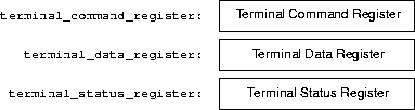
The constants terminal_command_register, terminal_data_register, and terminal_status_register give the Device-Space
addresses of the associated terminal registers.
The function of each terminal register is (the constant name in parenthesis
is the Device-Space address of register)
-
Terminal Command Register (
terminal_command_register) - Writing a value to the Terminal
Command Register starts a terminal operation.
Writing the value device::read to the Terminal Command Register
initiates terminal input: the next 8-bit character to arrive from the
terminal is stored in byte 0 of the Terminal Data Register.
Writing the value device::write to the Terminal Command Register
initiates terminal output: the contents of byte 0 in the Terminal Data
Register is sent to the terminal.
A terminal-io command begins as soon as a command is written to the command
register, using the value contained in the data registers (if writing). Once
a command is started, writing a new value into the data register has no
effect on the in-progress operation.
Any value other than device::read or device::write written to the
Terminal Command Register is interpreted as an illegal command code.
-
Terminal Data Register (
terminal_data_register) - The contents byte 0 in the Terminal Data
Register is the most recent 8-bit value either read from or written to the
terminal, depending on the value written to the Terminal Command Register.
-
Terminal Status Register (
terminal_status_register) - The Terminal Status Register
contains the status of the most recently issued terminal i-o operation. The
Status Register is a read-only register; the contents of the Terminal Status
Register is undefined until the most recently issued terminal i-o operation
is finished. Possible contents of the Terminal Status Register and their
interpretations are
status::ok | command completed successfully |
status::bad_command | unrecognized command |
The hardware architecture's execution behavior is so simple and generic that
you should already have a fairly good general idea of how it behaves.
This section describes some aspects of hardware execution you need to
keep in mind when designing your operating system.
A
process address space is the contiguous range of valid addresses in
which a process executes.
The structure of a process address space depends on whether the associated
user process runs under virtual memory or not (see the the Program
Status Register description to determine how a user process runs under
virtual memory or not).
Under virtual memory, the process address space comprises 2048 words; a
virtual address contains 11 bits. The valid virtual addresses in a process
address space range from vmem_base (inclusive) to vmem_top
(exclusive). A process need not occupy all its process address space; if it
does not, then any attempt to access an address in the unoccupied area of
the process address space should cause an invalid address interrupt.
A process address space is broken up into 64 pages, where each
page
is a contiguous sequence of 32 words. The pages are numbered from 0 to 63,
where page 0 contains address vmem_base and page 63 contains address
vmem_top - 1.
Given an 11-bit virtual address va, the leftmost 6 bits of va
determine the
page number associated with va; the rightmost 5
bits of va determine the
page offset within the page at which
the word addressed by va lies.
If virtual memory is not in enabled
The physical process-address space comprises the 1024 words making up
User Space. The valid addresses in a physical process address space
range from usr_base (inclusive) to usr_top (exclusive). A process
need not occupy all its physical process address space; if it does not, then
any attempt to access an address in the unoccupied area of the physical process
address space should cause an invalid address interrupt.
A physical address is interpreted as the 10-bit address of a word in User Space
and is not further broken down into component values.
If a user process is executing under virtual memory, then every address
va issued by the CPU is run through the Memory Management Unit
(MMU) to determine where - or if - the page holding va resides in user
space.
Upon receiving the virtual address va, the MMU looks for a
process-table entry having the following characteristics:
If such a page-table entry exists, the MMU translates va into a physical
address in User Space; otherwise the MMU throws an invalid address
interrupt. When the MMU throws an invalid address interrupt, the PC is
reset to point to the instruction containing the invalid address.
If a user process is not executing under virtual memory, then every address
issued by the CPU is used to access user space directly without translation.
An
interrupt changes execution mode from user mode to system mode. At
the same time, the interrupt changes the code being executed. Interrupts don't
occur in system mode; any interrupts raised during system mode are queued and
re-raised when user mode is re-established.
There defined interrupts are (the constant name in parenthesis is the
identifying value):
-
Illegal instruction interrupt (
illegal_instruction_i) - Occurs when the CPU
encounters an instruction it doesn't understand.
-
Reboot interrupt (
reboot_i) - Occurs on system start-up.
-
System-call interrupt (
system_call_i) - Occurs when the SYSC instruction is
executed.
-
Invalid address interrupt (
invalid_address_i) - Occurs when the executing
program attempts to access an address that is either non-existent or outside
the legal range defined by user mode.
-
Disk interrupt (
disk_i) - Occurs when the disk finishes the most recently
initiated I-O operation.
-
Terminal interrupt (
terminal_i) - Occurs when the terminal finishes the
most recently initiated I-O operation.
-
Countdown interrupt (
countdown_i) - Occurs when a countdown reaches zero.
The
interrupt vector is a set of seven words in System Store that gives
the addresses of the code that executes when an interrupt occurs. The
interrupt vector occupies storage just above the register set:
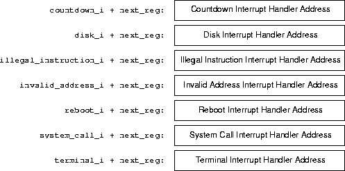
The contents of each word is interpreted as the starting address of the code
which will be executed when the associated interrupt occurs.
The disk and the terminal have essentially the same execution behavior, and
so will be described together using the generic term "device".
A device begins an operation as soon as a value is written into its Command
Register. The device copies the values stored in the argument registers into
internal registers at the start of the operation; the argument registers may be
rewritten without effecting the operation in progress. Remember:
A device begins an operation as soon as a value is written into its Command
Register.
The appropriate interrupt (disk or terminal) is raised when the
operation in progress ends. The contents of the Status Register for the
operation in progress is undefined until the interrupt is raised. Writing a
value into a Command Register always results in an interrupt, even when the
status indicates an error.
Writing a value into a Command Register always starts a new operation. If an
operation is in progress when a value is written into the Command Register, it
is cancelled and a new operation is started. This behavior occurs whether or
not the new operation succeeds or fails.
This page last modified on 17 September 2003.