See the assignment turn-in page (last modified on 14 January 2006) for instructions on turning in your assignment.
A port can either be an input port or an output port. An input port has zero input wires and one or more output wires. An output port has one or more input wires and zero output wires. An output port with more than one input wire acts like an or component.
Each logic-circuit component has a propagation time, which is the amount of time it takes for input values to move across the component and become output values. For an logic-circuit component with multiple inputs and outputs, assume that all input values to the component show up at the same time and all output values are produced at the same time; also assume the number of inputs and outputs has no effect on the propagation time. The and, or, and not logic-circuit component have a propagation time of one unit; the switch logic-circuit component has a propagation time of two units. Ports and wires have a propagation time of zero units (that is, value transmission is instantaneous).
A number is a sequence of one or more decimal digits.
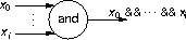
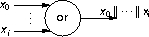
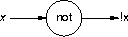
name representing andand logic-circuit component oror logic-circuit component notnot logic-circuit component switchswitch logic-circuit component ininput port outoutput port
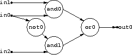
For example, the input
describes the logic circuitin0 and0 in1 not0 in1 and0 in2 and1 not0 and1 and0 or0 and1 or0 or0 out0
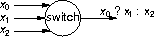
The first wire connected to a switch is the control signal (that is x0 in the diagram above). The second wire connected to the same switch is the true signal, and the third is the false signal.
A switch should have three inputs; a not component should have one input. Switches or not components that don't have the proper number of inputs should result in an informative error message and the program should halt without further processing.
0 or 1. Placing the input-port names in alphabetical order,
the ith input port is assigned the value bi. Each input-value set
appears on a single line, and each input line contains at most one input-value
set.
Each input-value set read should result in a single line of output. If no errors were detected, then the total propagation time for the values through the circuit followed by the output-value set should be written to std-out. The propagation time should be separated from the output-value set by at least one space character.
An output-value set has the same format as an input-value set: it's a sequence
of n zeros and ones b1, b2, ... bn, where n is
the number of output ports defined in the circuit and bi is either
0 or 1. Placing the output-port names in alphabetical order, the
ith output port produced the value bi.
Any errors detected while reading an input-value set should cause the program to print an informative error message on std-err and wait for the next input-value set.
gen-input, available in the class assignment directory
/export/home/class/cs-503/a5, to generate input for your program. When run, it writes
an randomly generated logic-circuit description to std-out, followed by
some randomly generated input-value sequences You can use it with your program
like so:
Because$ ./gen-input | ./circuit-analysis
gen-input creates new input each time it's run, you might find it
more convenient to save the input in a file to provide your program with
consistent input:
$ ./gen-input > input

$ ./circuit-analysis < input
| This page last modified on 13 April 2006. |