A continuous-feed laser printer is similar to a regular laser printer
except that it prints on rolls of paper rather than sheets of
paper. Continuous-feed laser printers are used in information-stream recording
devices, such as seismographs, EKG machines, and cash registers.
For this assignment, a continuous-feed laser printer can be thought of as a
computer with two special devices: the paper roll and the print bar.
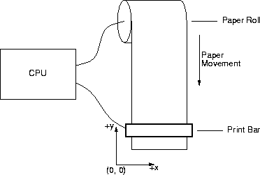
The paper-roll coordinate system has the origin at the lower left-hand corner
of the paper, with positive x increasing to the right and positive y increasing
up. The paper roll has (essentially) an infinte y extent, but only a
finite x extent, given by the width of the print bar. The paper roll can
only be moved forward, that is, towards higher y values.
The print bar can be thought of as a vector of pixels. If a pixel is set,
it will leave a mark on the paper; an unset pixel leaves no mark. A pixel must
be either set or unset. Pixels are indexed by the numbers 0 through
x_extent - 1, where x_extent is the width of the print bar in pixels;
pixel 0 is the left-most pixel in the print bar.
A continuous-feed laser printer works by running software that reads its input,
which contains a description of what to print, and manipulating the paper roll
and print bar according to what it has read from input. The output is a piece
of paper with marks on it, drawn according to the description given in input.
In this assignment, you will write the software that runs on a continuous-feed
laser printer. Your software will be in the form of a program that can be run
from the command line.
Input
The input to a continuous-feed laser printer is given in a text file read from
standard input. The text file describes a sequence of zero or more line
segments. Each line segment is defined by four consecutive integers; the first
two integers give the x and y coordinates of one endpoint, the other
two integers give the x y coordinates of the other endpoint.
Successive integers in the input file are separated by at least one white-space
character. Line segments are measured in units of 0.01 of an inch.
For example, the input
50 50 100
150
produces the output consisting of a single line with one endpoint at (0.5 in,
0.5 in) and the other endpoint at (1.0 in, 1.5 in).
A line segment's endpoints are given in no particular order, and the line
segments in a file are listed in no particular order. A line segment need not
lie entirely within the bounds of the paper; it may extend past the three sides
of the paper. Only the line-segment parts actually on the paper should be
printed.
Hardware
Your software accesses the laser-printer hardware via a set of routines defined
in cflp.h in the directory /export/opt/cs-509/pa2. The routines are defined in the file
cflp.cc in the same directory; you should include it, or a compiled
version of it, along with your files:
CC -o cflp your files here /export/opt/cs-509/pa2/ cflp.cc
Output
If your software successfully interprets the input, the result will be a
PostScript file named cflp.ps in the same directory in which your software ran.
You can use the PostScript viewer gs to view cflp.ps without printing it.
The file /export/opt/cs-509/pa2/radii contains an image you can use as input to your program.
Oh, And One More Thing
To keep their price down, continuous-feed laser printers don't have a lot of
memory and use small, slow CPUs. Your software must accommodate these
characteristics by being efficient; in particular, your software should use no
more than O(nY) time and O(n + Y) space, where n
is the number of line segments in the input file and Y is the height of
the image's bounding box (that is, Y = Ymax - Ymin, where Ymin is the value of the smallest y coordinate
of any visible, set pixel in the image and Ymax is the value of
the largest y coordinate of any visible, set pixel in the image). You
may assume that all hardware operations take constant time.